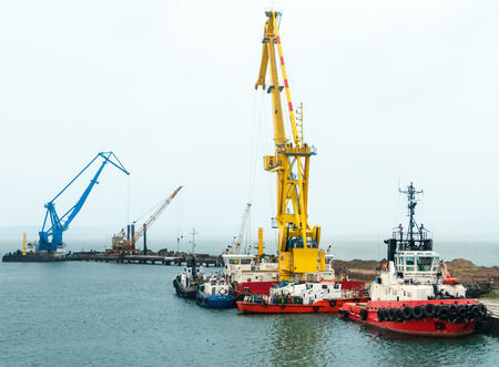
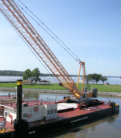
16.L.07 Floating Service Load Chart, LHE on Floating Platform.
The NAA and Floating Service Structural Analyses must be used to develop the Floating Service Load Chart.
- The Floating Service Load Chart will define the lift/radius capacity of the LHE on the specific floating platform.
- The Floating Service Load Chart must incorporate any de-ratings required by either the NAA or Floating Service Structural Analysis.
- An RPE or Naval Architect/Marine Engineer, competent in the field of floating crane/derrick design, must stamp and/or certify (sign) that the Floating Service Load Chart meets the requirements of Sections 16.L.05 and 16.L.06.
- The load chart certification may be either:
- A floating service load chart developed (de-rated) from the Manufacturer's floating service load chart, or
- If no de-rating is required, the Crane Manufacturer's Floating Service Load Chart with separate attached certification document.
- The Floating Service Load Chart and the Floating Service Naval Architect Analysis must be submitted to the GDA for acceptance prior to start of work.
- The Floating Service Load Chart must be posted in the cab or at the operator's station (if no cab). All other procedures applicable to the operation of the equipment (instructions and operators manual, recommended operating speeds, etc.) must be readily available on board.
- The Floating Service Load Chart must, at a minimum, include the following:
- (1) Naval Architect's Notes delineating:
- (a) Draft limits;
- (b) Deck cargo weight and Vertical Center of Gravity above deck;
- (c) Maximum wind speed;
- (d) Environmental limits;
- (e) Vessel heel and trim limits;
- (f) LHE Machine list and trim limits, and
- (g) Vessel condition (e.g., dry bilges, watertight integrity, etc.).
- (2) The LHE Manufacturer's Floating Service Crane Load Chart.
- (3) If de-rating of the Crane Manufacturer's Floating Service Crane Load Chart is required, a separate Floating Service Safe Working Load Chart must be provided with:
- (a) Mode of operation;
- (b) Table of hook load, boom elevation angle, lift radius (with list/trim considered);
- (c) Maximum Machine List and Trim;
- (d) Maximum Floating Platform List and Trim;
- (e) LHE configuration, to include boom length, amount of counterweight, parts of wire, and block size.
- The Floating Service Load Chart must be programmed into the crane LMI.
- The Floating Service Load Chart must remain valid so long as no major modifications are made to the LHE or to the floating platform, as documented by a QP.
16.L.08 Land LHE, derricks and mobile auxiliary LHE mounted on barges, pontoons or other means of flotation.
- All requirements in Sections 16.L.02 through 16.L.07 must be applicable for land- LHE, derricks and mobile auxiliary LHE mounted on barges, pontoons or other means of flotation.
- LHE Mats. The need, type, size and location of LHE mats required must be determined for the type of LHE on the barge.
- Means of attachment of LHE must be must be provided to prevent shifting during lift operations. The attachment method must not be used to hold down LHE against overturning moment.
16.L.09 LHE Travel.
- If traveling is required on the barge with no load, the travel area must be evaluated in the NAA, and identified on the Floating service Load Chart.
- If traveling is required while lifting the load, the lift must be deemed a critical lift and a critical lift plan is required.
- If traveling is required while lifting the load, the requirements in Sections 16.L.02 through 16.L.07 must be satisfied throughout the travel range. The NAA and Structural Analyses must cover the travel range with load. The travel area must be evaluated in the in the NAA, and identified on the Floating Service Load Chart.
16.L.10 A-Frame Non-Slewing Anchor Handling Barge/Vessel.
- A-Frame Non-Slewing anchor handling barge/vessels may be used for anchor handling, low lifting of loads such as anchor buoys/weights, dredge pipe, submerged pipeline and pontoons.
- Note: If used for any other lifting application, the work platform will be considered a floating derrick and all other requirements of Section 16 apply.
- A-Frame Non-Slewing anchor barge/vessels must also comply with the following:
- (1) All deck surfaces of the pontoon or barge must be above the water;
- (2) Means for limiting the applied load, such as mechanical means or marking the draft of the barge corresponding to the rated load, must be provided. Calculations must be available and the barge must be tested to verify rated load;
- (3) A ratchet and pawl must be provided for releasing the load from the hoisting machinery brake;
- (4) An operating manual/procedure must be available for use by the operator. The operator must be trained in the anchor handling barge systems operation.
- If additional external load is superimposed above that which can be hoisted with the onboard hoisting machinery, then a chain stopper must be used to remove the external load from the A-frame and hoist machinery.
16.L.11 Employer-Made Lift Equipment Used on Barges or Pontoons.
- If lift equipment is employer-made, it must not be used unless the employer has documents demonstrating that the load charts and applicable parameters for use meet the requirements of one of the standards identified in Section 16.L.02.
- All requirements in Sections 16.L.02 through 16.L.07 must be applicable.
16.L.12 Modifications.
- Weight and Center of Gravity (CG) changes. Any modifications to the Crane and Floating Platform that result in any of the following changes to the crane and floating platform lightship characteristics must require a new Naval Architect Analysis, and a new Floating Service Load Chart:
- (1) An increase in Vertical CG by more than 2 in (5 cm);
- (2) A change in the lightship displacement by more than 3 (degrees), or
- (3) A shift in Longitudinal CG of more than 1 of floating platform length.
- Modifications to the crane that result in changes to the crane lift capacity and/or to the crane machine list and trim limits must require a new NAA, and a new Floating Service Load Chart.
16.L.13 Overhead Bridge Cranes On Floating Platforms.
- An overhead bridge crane Naval Architectural Heel and Trim Analysis must be performed for overhead bridge cranes on floating platforms by a RPE or Naval Architect/Marine Engineer, competent in LHE on floating plant.
- (1) The Analysis must determine the maximum vessel heel and trim that can be generated by use of the bridge crane.
- (2) The Analysis must cover the full longitudinal and transverse motion range of the bridge crane, the crane weight, and the crane full rated load.
- (3) If floating platform heel and trim not related to the bridge crane operation is present during the bridge crane operation, the non-related heel and trim must be included in the Bridge Crane Naval Architectural Heel and Trim Analysis.
- (4) A RPE or Naval Architect/Marine Engineer, competent in the field of floating crane/derrick design, must stamp and/or certify (sign) that the Bridge Crane Naval Architectural Heel and Trim meets the Analysis requirements of this Section.
- Bridge Crane Operation at floating platform heel and trim. The bridge crane manufacturer must verify that the bridge crane may be safely operated at the vessel heel and trim maximums identified by the Bridge Crane Naval Architectural Analysis.
- Floating Platform heel and trim indication. A heel and trim indicating device must be provided on all bridge crane equipped floating platforms. The indicating device must be visible by the bridge crane operator during bridge crane operation.
Knowledge Check Choose the best answer for the question.
16-18. What is required when a modification to a crane that result in changes to the crane lift capacity and/or to the crane machine list and trim limits?
You forgot to answer the question!


